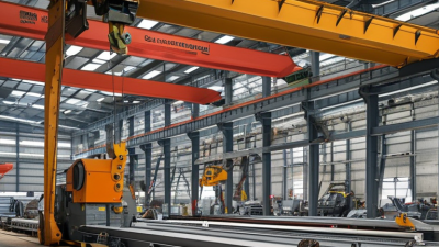
Steel fabrication machinery shapes the accuracy, speed, and safety of modern metalworking projects. Yet choosing equipment is rarely as simple as comparing motor power or purchase prices. A machine that performs well in a large structural steel plant may create unnecessary costs in a smaller workshop.
Experienced fabricators usually begin with the workpiece, not the brochure. Plate thickness, beam size, steel grade, tolerance requirements, and expected production volume all affect the decision. Cutting, drilling, bending, welding, and finishing equipment each demand different checks. Watch the machine operate. Listen for vibration. Inspect the control panel, guarding, tooling access, and maintenance points. Small details often reveal more than polished specifications.
Reliable guidance also comes from verifying service support, spare-part availability, operator training, energy use, and documented safety features. Ask suppliers for references from facilities with similar workloads. Request test cuts or sample results when possible. Claims should be measurable. “High precision” needs a tolerance, and “fast production” needs a cycle time.
These seven tips focus on practical choices for steel fabrication machinery, from matching capacity to evaluating total ownership costs. They also leave room for doubt. No checklist can predict every breakdown, awkward workflow, or future production change. A careful buyer should challenge assumptions, record real operating conditions, and admit when a cheaper machine may not be the wiser investment. Good equipment is not merely powerful. It should fit the people, materials, space, and standards surrounding it.
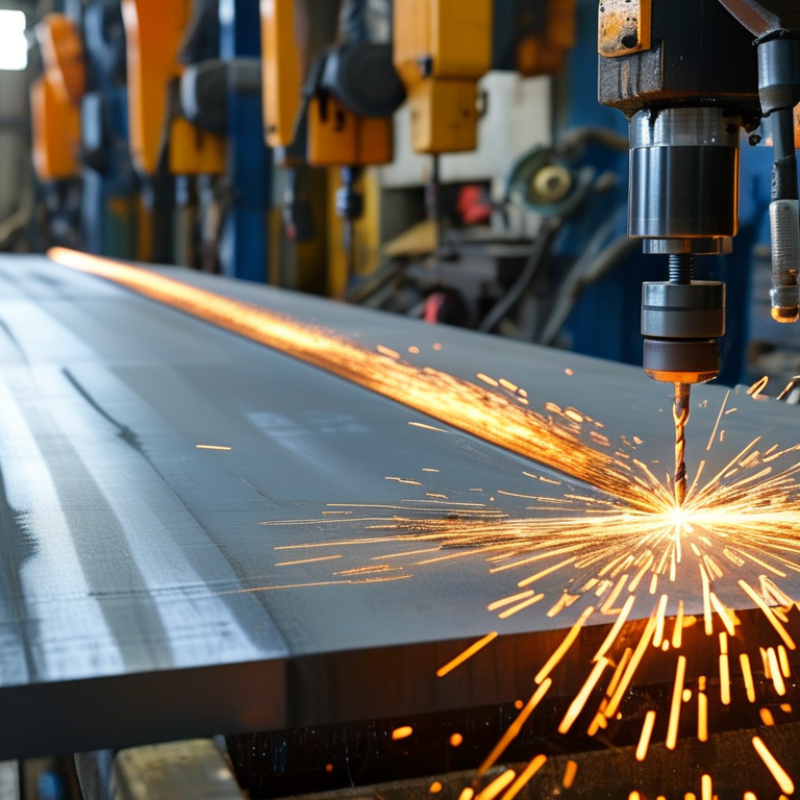
Before choosing steel fabrication machinery, define the material range precisely. S235 and S355 are not interchangeable in daily production. S235 offers lower yield strength, while S355 generally needs higher forming force. Check the material certificate, not only the label on the delivery note. This small habit prevents costly assumptions.
Record the required thicknesses beside each grade. A workshop may process 3 mm sheet one day and 25 mm plate the next. Cutting capacity, press brake force, tooling width, and welding settings must match those changes. Thick S355 plate can demand slower cutting, stronger clamping, and careful heat control. Thin sheet brings different problems, including distortion and edge damage. Practical trials help. A test cut of 12 mm plate can reveal more than a catalogue table.
I have seen teams select machinery around their average thickness, then struggle with occasional heavy plates. That decision looked efficient, but it reduced flexibility. It is also worth checking thickness tolerances and plate flatness before calculating capacity. Real material rarely behaves as neatly as a spreadsheet suggests. One overlooked detail is the reduced yield strength listed for some thicker sections. Ask the supplier for verified mechanical data. Keep records of cutting speed, bending force, and weld performance. These notes turn experience into reliable specifications, although the first estimate may still need correction.

Tip 1: Define the real plate range. A machine rated for 6–25 mm may not cut 25 mm continuously. Check recommended thickness, not only maximum thickness.
Tip 2: Match the process to the material. The World Steel Association recorded 1.892 billion tonnes of crude steel production in 2023. That scale reflects diverse grades, strengths, and thicknesses. Confirm tensile strength before selecting cutting power.
Tip 3: Inspect the cutting bed. Leave space for loading, clamps, and thermal distortion. A narrow bed can turn a suitable machine into a daily bottleneck.
Tip 4: Calculate bending tonnage for your longest bend. Tonnage depends on thickness, bend length, tensile strength, and die opening. A 25 mm plate needs dramatically more force than a 6 mm sheet.
Tip 5: Check the frame’s working length. Buying high tonnage with a short bed is an easy mistake. It may force multiple bends and visible alignment marks.
Tip 6: Compare duty cycles, not impressive peak ratings. OECD steel market reviews reported more than 500 million tonnes of global excess capacity in recent assessments. Demand can shift, so avoid sizing only for optimistic forecasts.
Tip 7: Request a sample trial. Test 6 mm, 12 mm, and 25 mm material using your actual grades. Record edge quality, angle accuracy, cycle time, and scrap. ISO 9013:2017 provides useful thermal-cutting quality references, but shop conditions still matter. I would not trust a brochure alone; operators often expose limitations that specifications hide.
| Tip | Capacity Check | Practical Data Range | Recommended Machine Specification | Selection Guidance | Important Verification |
|---|---|---|---|---|---|
| 1 | Match the maximum plate thickness | 6–25 mm carbon steel | Choose a rated cutting capacity at least 10–20% above the thickest regularly processed plate. | For a 25 mm requirement, consider a machine rated for approximately 28–30 mm mild steel to allow for material variation and production wear. | Cutting capacity depends on steel grade, tensile strength, heat-affected-zone limits, edge quality, and the selected cutting process. |
| 2 | Select the right cutting process | 6–12 mm: plasma or laser 12–25 mm: high-power plasma or oxy-fuel |
Use fiber laser for high-speed thin-to-medium plate work; use plasma for flexible production; use oxy-fuel when cutting very thick carbon steel is the priority. | For repeated 20–25 mm carbon-steel work, a high-definition plasma or oxy-fuel setup can be more practical than a thin-sheet laser system. | Compare kerf width, piercing time, bevel angle, consumable cost, fume extraction, and required surface quality—not only rated thickness. |
| 3 | Calculate press-brake tonnage | Typical air-bending guide: about 60–90 tonnes per metre for each 1 mm of mild-steel thickness |
For example, bending 6 mm mild steel over a 2,000 mm length may require roughly 720–1,080 tonnes, depending on the V-opening, tooling, material strength, and bend radius. | Choose tonnage from the actual bend length and tooling setup. Do not size the press brake from plate thickness alone. | Confirm the manufacturer’s force chart. Narrow V-openings, stainless steel, high-strength steel, and bottoming or coining operations can significantly increase required force. |
| 4 | Check bed size and working envelope | Common fabrication beds: 1,500 × 3,000 mm 2,000 × 4,000 mm 2,000 × 6,000 mm |
Select a cutting bed at least 100–300 mm longer and wider than the largest frequently processed part when loading and nesting space are considered. | A 2,000 × 4,000 mm bed suits many medium-size structural parts; a 2,000 × 6,000 mm bed reduces repositioning for long beams, frames, and panels. | Measure the full sheet, usable cutting area, loading clearance, slat support, and available floor space before ordering. |
| 5 | Verify bending length and throat depth | Typical press-brake lengths: 2,000–4,000 mm Common throat depths: 250–400 mm |
Choose a bending length longer than the largest bend line, with sufficient throat depth for the part’s flange and return dimensions. | For long panels, a 3,000–4,000 mm bending length can reduce part repositioning and improve angle consistency across the workpiece. | Check daylight opening, stroke, crowning, back-gauge travel, segmented tooling length, and maximum workpiece weight. |
| 6 | Match accuracy to the finished part | Typical CNC positioning capability: approximately ±0.05–±0.10 mm Typical cut-edge tolerance varies by process and thickness |
Use CNC control, automatic height sensing, stable clamping, and suitable tooling when repeatability is important. | For structural brackets and general fabrication, standard CNC control may be sufficient; tighter assemblies may require calibrated axes, compensation, and inspection routines. | Request test cuts or sample bends using the same thickness, grade, tooling, and programming method planned for production. |
| 7 | Confirm utilities, safety, and total operating cost | Typical requirements include: three-phase power, compressed air, ventilation, fume extraction, lifting access, and guarding |
Size the electrical supply, air compressor, extraction system, chiller, consumables, and material-handling equipment for the selected capacity. | A machine that meets thickness requirements but lacks sufficient power, extraction, cooling, or crane access can reduce productivity and create safety risks. | Review emergency stops, interlocks, laser or plasma fume controls, operator training, spare parts, preventive maintenance, and annual consumable costs. |
Tip 1: Set a measurable cut-quality target before comparing steel fabrication machinery. ISO 9013 cut classes provide a practical reference for thermal-cutting quality. They help you assess edge angle, surface roughness, and visible imperfections. Do not accept “clean cuts” as a complete specification. Ask for the required class on your actual steel thickness.
Tip 2: Treat ±0.1 mm positioning as a verification target, not a marketing phrase. Positioning accuracy depends on calibration, drive condition, thermal expansion, material flatness, and cutting speed. Request a test coupon using your common plate size. Measure hole centers, profiles, and repeated movements with calibrated equipment. A machine may reach ±0.1 mm in controlled conditions, but production results can differ. This is where many buying decisions become too optimistic.
Tip 3: Inspect the cut in the workshop, not only on paper. Check dross, bevel variation, kerf width, and small-hole accuracy under consistent lighting. Record results across several sheets. ISO 9013 classes are useful, yet they do not remove operator influence or maintenance problems. I have seen excellent trial cuts deteriorate after neglected torch alignment. Keep a simple inspection log. It exposes weak assumptions. A slightly slower machine may produce more reliable parts when calibration is easy and repeatable. Your target should reflect real fabrication work, including temperature changes, mixed thicknesses, and occasional imperfect plate.
When choosing steel fabrication machinery, productivity should be measured, not guessed. Cycle time shows how long one completed part takes under defined conditions. Record loading, cutting, forming, unloading, and minor adjustments. A machine may promise a six-minute cycle. The shop floor may show nine. That difference matters. Measure at least thirty consecutive parts during a normal shift. Exclude unusual prototypes, but keep routine interruptions visible. This creates a more honest production picture.
Calculate eight-hour output from the verified cycle time. A six-minute cycle suggests 80 parts before breaks and losses. Real output is usually lower. Material changes, inspection, tool wear, and operator decisions consume minutes. Do not hide them. An 85% OEE target adds another layer. It combines availability, performance, and quality. Ask for the assumptions behind that figure. Clarify shift length, staffing, material thickness, setup frequency, and acceptable defect rates. A line producing 68 good parts from an 80-part theoretical target may look strong. However, scrap can distort the calculation. Track good parts separately. Use a daily sheet for planned time, run time, total count, and rejects. My first estimate was too optimistic because setup time was missing. That mistake changed the payback calculation. Leave room for maintenance and operator learning. Productivity improves when measurements remain visible, repeatable, and slightly uncomfortable.
Compare cycle time, 8-hour output, and the 85% OEE benchmark across common steel fabrication equipment.
Shorter cycle times and higher eight-hour output indicate greater production capacity. OEE combines availability, performance, and quality; an 85% OEE level is widely used as a strong operational benchmark. Actual results vary with material thickness, part complexity, setup time, staffing, and maintenance.
Choosing steel fabrication machinery requires more than comparing cutting speed and purchase price. Audit the safety file before requesting a discount. In the United States, OSHA 29 CFR 1910.212 requires guarding against points of operation, rotating parts, and flying chips. For European use, verify the CE declaration, risk assessment, technical file, and safety instructions. CE marking is not a quality award. It shows conformity with applicable requirements.
Check the pneumatic specification beside the machine. Many fabrication systems operate near 6–8 bar, but pressure alone proves little. Ask for air consumption at the rated cycle, required flow in cubic metres per minute, filtration class, and moisture limits. The U.S. Department of Energy reports that compressed air can represent about 10% of industrial electricity use, with higher shares in some plants. A small leak sounds harmless. It is not. Measure it during idle hours.
Build a five-year ownership model. Include tooling, electricity, compressor loading, calibration, planned maintenance, operator training, and disposal. ISO 15686-5 identifies life-cycle costing as a method for evaluating costs beyond the initial purchase. Request service intervals and replacement-part prices in writing. A low quote may hide expensive downtime. I have seen spreadsheets omit installation and extraction equipment. That mistake can distort the result badly. Leave room for uncertainty, because production volume rarely matches the sales forecast.