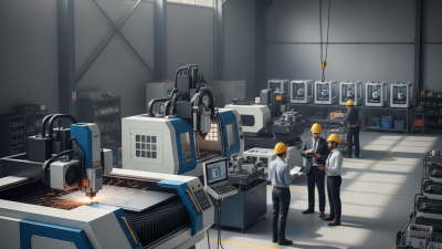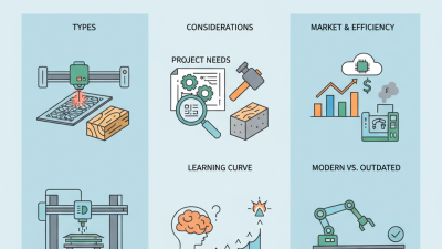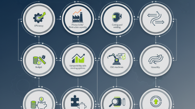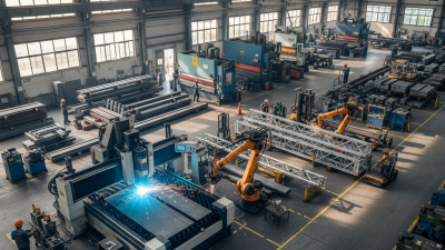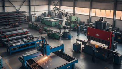
Choosing a fabrication machine in 2026 requires more than comparing prices and cutting speeds. It requires evidence, process knowledge, and a realistic view of daily production. A laser cutter may deliver clean edges on 6-millimeter steel, while a press brake may determine the actual bottleneck. The right choice depends on material thickness, batch size, tolerances, floor space, energy use, and operator skill.
Industry data supports a careful approach. The International Federation of Robotics reported 542,000 industrial robots installed worldwide in 2023, showing continued investment in automation. Deloitte’s 2025 Manufacturing Industry Outlook also identifies labor shortages, digital transformation, and cost pressure as major manufacturing concerns. These trends make automation attractive, but automation is not automatically profitable. A highly capable fabrication machine can remain underused if programming takes too long or service support is weak.
Look beyond the brochure. Ask for verified cycle-time tests using your material, including loading, tooling changes, and inspection. Check electrical requirements, spare-part availability, software compatibility, training, and the supplier’s response time. Energy performance also deserves attention, especially when machines run across multiple shifts. Reports offer useful direction, but they rarely reflect your workshop’s dust, humidity, operators, or inconsistent steel quality. That limitation matters. A confident purchase can still be wrong. In 2026, the strongest decision combines published data with a documented trial, total-cost analysis, and honest feedback from the people who will use the machine every day.
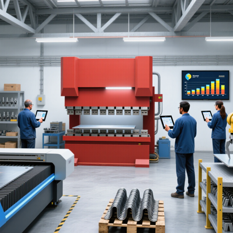
Choosing a fabrication machine should begin with the drawing, not the machine catalog. ISO 2768 helps define general tolerances when individual limits are missing. Its tolerance classes, such as fine, medium, coarse, and very coarse, affect cutting, forming, drilling, and inspection decisions. A medium class may suit structural parts, but it can be unsuitable for fitted components.
Read every feature carefully. Hole position, bend angle, edge straightness, and material thickness can demand different capabilities. A laser cutter may produce clean profiles, while a press brake must control springback and angle variation. For a 1,000-piece batch, repeatability often matters more than the fastest single cycle. For ten prototypes, flexible setup can save more money.
Batch size changes the decision.
Small batches usually favor quick programming, simple tooling, and accessible maintenance. Large batches may justify automated loading, dedicated fixtures, and in-process measurement. Still, automation does not repair an unclear tolerance strategy. I have seen teams select impressive equipment before checking inspection costs, which later damaged the schedule. That mistake is easy to repeat. Review the latest ISO requirements, confirm material behavior with test pieces, and compare the machine’s proven accuracy against the drawing. Leave a practical margin; quoted accuracy and factory-floor accuracy are not always identical.
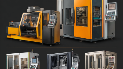
How to Choose a Fabrication Machine in 2026?
Selecting a fabrication machine starts with the material, part geometry, and production target. Cutting machines usually offer high speed and clean dimensions, especially on repeatable profiles. Their accuracy depends on beam stability, fixture control, and material thickness. Forming machines work differently. They trade speed for controlled force, tool alignment, and springback management. A formed edge may look precise but still need measurement after release.
Welding equipment should be judged by heat input, penetration, and distortion control. Heat input roughly follows voltage multiplied by current, divided by travel speed. Too much heat can warp thin sheet or enlarge the heat-affected zone. Too little may create weak fusion. In practical shop trials, I measure cut deviation, bend angle, weld distortion, and cycle time on the same material batch. A spreadsheet helps, but it can hide operator skill and maintenance problems. That part is easy to underestimate.
Tips: Test real parts, not only sample coupons. Record setup time. Check tolerances after cooling. Ask whether technicians can service the machine safely. Keep one imperfect trial; it often reveals where the process is fragile. Speed matters. Repeatability matters more.
| Process / Machine Type | Typical Material Range | Typical Production Speed | Typical Accuracy | Heat Input / Thermal Effect | Best-Suited Applications | Main Selection Consideration |
|---|---|---|---|---|---|---|
| Fiber Laser Cutting | Carbon steel, stainless steel, and aluminum; approximately 0.5–25 mm, depending on power and material | About 1–20 m/min on thin and medium-gauge sheet; slower on thick plate | Approximately ±0.05–0.15 mm under stable operating conditions | Low to moderate localized heat input; narrow heat-affected zone, commonly below about 0.5 mm on thin sheet | Precision sheet-metal parts, enclosures, brackets, panels, and intricate profiles | Choose based on laser power, sheet thickness, nesting efficiency, assist-gas cost, and required edge quality |
| CNC Plasma Cutting | Mainly carbon and stainless steel; approximately 3–50 mm, with high-definition systems used for thinner sheet | About 1–8 m/min, depending on amperage, thickness, and cut quality requirements | Approximately ±0.2–0.5 mm for a well-tuned CNC system | Moderate to high localized heat input; HAZ commonly about 1–3 mm, varying with thickness and parameters | Medium and heavy plate, structural components, machinery parts, and large-format profiles | A practical choice when cutting speed and thickness capability matter more than laser-level edge precision |
| Oxy-Fuel Cutting | Primarily carbon steel plate; commonly ่อย 10–300 mm or more with suitable equipment | About 0.2–1.5 m/min, depending strongly on plate thickness | Approximately ±0.5–1.5 mm; generally lower than laser or high-definition plasma | High thermal effect; HAZ may extend several millimeters and can increase distortion risk | Very thick carbon-steel plate, structural fabrication, repair work, and outdoor applications | Best when thick carbon steel and low equipment cost are more important than speed or fine accuracy |
| CNC Press Brake | Sheet and plate from approximately 0.5–25 mm, depending on machine tonnage, tooling, and bend length | Typically 5–15 bends per minute; actual output depends on part geometry and handling time | Bend-angle accuracy commonly about ±0.5–1°; back-gauge positioning may reach approximately ±0.05–0.1 mm | Negligible heat input in normal cold forming; no heat-affected zone | Boxes, channels, frames, covers, cabinets, and one-off or varied fabricated parts | Evaluate tonnage, bend length, tooling flexibility, crowning, angle measurement, and programming functions |
| Roll Forming Line | Coiled carbon steel, galvanized steel, stainless steel, and aluminum; commonly 0.4–6 mm | Approximately 10–60 m/min for continuous profiles, depending on profile complexity | Typical profile dimensional tolerance about ±0.2–0.5 mm with properly set tooling | Negligible heat input in cold forming; potential residual stress if tooling is poorly designed | High-volume channels, rails, studs, roofing profiles, frames, and long constant-section parts | The strongest option for repeatable, high-volume profiles; less suitable for frequently changing shapes |
| MIG/MAG Welding | Carbon steel, stainless steel, and aluminum; commonly used from about 1.5 mm to heavy sections with multipass welding | Travel speed typically 0.3–1.2 m/min; deposition rate often about 2–8 kg/h, depending on wire size and current | Finished assembly accuracy commonly about ±0.5–2 mm, strongly influenced by fixturing and distortion control | Moderate to high heat input, commonly about 0.4–1.5 kJ/mm after process-efficiency correction | General fabrication, frames, machinery, structural assemblies, and medium-to-high production volumes | Prioritize duty cycle, wire-feed stability, shielding-gas control, joint access, and automated or robotic compatibility |
| TIG Welding | Stainless steel, aluminum, titanium, and thin carbon steel; commonly about 0.5–6 mm per pass | Typically 0.1–0.5 m/min, depending on joint design and material thickness | High weld-bead control; finished assembly accuracy commonly about ±0.3–1.0 mm with good fixturing | Low-to-moderate travel speed with concentrated heat; typical heat input about 0.2–1.0 kJ/mm | Visible welds, thin sections, sanitary equipment, precision components, and reactive alloys | Select when weld appearance, cleanliness, and control are more important than maximum throughput |
| Resistance Spot Welding | Overlapping sheet metal, commonly approximately 0.5–3 mm total thickness per weld stack | About 20–60 welds per minute in automated or dedicated production cells | Excellent repeatability; joint-location accuracy commonly about ±0.2–0.5 mm with rigid fixtures | Very localized heat input, typically about 0.1–1.0 kJ per weld; short weld cycles limit overall distortion | High-volume sheet assemblies, brackets, housings, frames, and overlapping lap joints | Best for repetitive joints; it requires access from both sides and is not suitable for every joint geometry |
The work envelope should match real parts, not optimistic drawings. Measure the longest sheet, tube, or assembly you regularly handle. Then add clearance for clamps, edge waste, and operator access. A useful starting point is 10% extra space, though irregular parts can demand more.
Deloitte’s 2024 Smart Manufacturing Survey found that 86% of manufacturers expect smart production to remain important for competitiveness. That pressure makes flexible sizing valuable, but a larger bed is not automatically better. It can increase floor space, energy use, and maintenance costs.
Material thickness must guide the machine’s power, tooling, and rigidity. List your common thicknesses, then identify the occasional maximum. Do not size the entire machine around one rare job. Cutting charts are helpful, but actual results change with alloy, heat buildup, surface condition, and consumable wear.
ISO 230-1 provides a recognized framework for testing machine-tool accuracy. Ask suppliers for measured accuracy data, not only brochure tolerances.
Duty cycle is often underestimated. Record daily operating hours, peak production periods, and idle intervals. The U.S. Energy Information Administration reported that industry used about 35% of U.S. electricity in 2023, so inefficient operation can become a visible cost.
Check spindle ratings, cooling capacity, service intervals, and thermal stability. I have seen machines selected for maximum thickness, then underused for months. That choice deserves a second look.
A smaller, rigid machine may deliver better repeatability and lower ownership costs.
Choosing a fabrication machine in 2026 should begin with measured motion, not brochure resolution. ISO 230-2:2014 separates positioning accuracy from repeatability. That distinction matters. A machine may reach a coordinate once, then miss it after thermal drift or reversal. For production, specify repeatability below 0.05 mm at the actual work zone. Ask for bidirectional tests, axis-by-axis data, and test temperatures.
ISO 230-2 evaluates multiple target positions and approach directions. NIST Technical Note 1297 recommends reporting measurement uncertainty with a coverage factor of k=2, commonly linked to about 95% confidence. Therefore, a reported 0.04 mm result is incomplete without uncertainty. If uncertainty is ±0.02 mm, the practical margin becomes uncomfortable. Require raw test records, probe calibration dates, warm-up time, feed rate, and compensation status. Small details decide large contracts.
During acceptance, repeat a hole pattern after several hours, not only after warm-up. Check aluminum and steel parts separately. Thermal behavior differs. VDI/DGQ 3441 also supports evaluating scatter across repeated positioning cycles, giving buyers a useful comparison method. I would reject a clean certificate without an environmental log. That may sound strict. It remains sensible. One weakness remains: 0.05 mm on the machine may not mean 0.05 mm on the finished part. Tool wear, fixturing, and cutting forces can erase the margin.
Choosing a fabrication machine in 2026 requires more than comparing cutting speed or purchase price. In a real workshop, operators notice safety weaknesses quickly. Check fixed guards, emergency stops, interlocks, noise, dust control, and access around moving parts. Ask whether maintenance staff can isolate energy safely. A machine that saves minutes but creates awkward service work may increase risk.
Total cost should include installation, training, tooling, energy, calibration, software, spare parts, and planned downtime. Request realistic production data, not only the best shift record. A useful calculation compares annual output with these continuing expenses. For example, frequent nozzle changes or unstable tolerances can quietly reduce profit. The cheapest quotation is not always the lowest-cost choice.
ISO 22400 offers a structured method for measuring manufacturing performance. Its OEE approach examines availability, performance, and quality. The 85% figure is a demanding benchmark, not a universal legal requirement. Treat it as a reference point, then compare it with your process, material, and staffing conditions. Record short stops, rejected parts, and setup delays honestly. Otherwise, the result may look impressive but teach little. An imperfect first measurement is still useful. Review it with operators each month, and question any number that seems unusually clean.
Assess Safety, Total Cost, and the ISO 22400 OEE Benchmark of 85%
This illustrative decision model compares three anonymous machine profiles using measurable selection criteria: safety-control coverage, five-year total cost of ownership, and overall equipment effectiveness (OEE). OEE is calculated as Availability × Performance × Quality. The 85% level is widely used as a planning benchmark; ISO 22400 defines manufacturing KPI methods but does not mandate a universal OEE threshold.